Iranian Classification Society Rules

< Previous | Contents | Next >
Annex 2-5 Guidance for non-destructive examination of hull machinery steel forgings
and
1. Application
(1) The requirements in this Guidance is intended to give general guidance on the and recommended quality levels applicable to the non-destructive examinations
extent, methods (NDE) of steel
forgings(hereinafter referred to as "forgings") specified in Ch 1, 601. 8 and 10 of the Rules.
(2) For steel forgings(e.g. components for couplings, gears, boilers and pressure vessels) other than those specified in this Guidance, the requirements in this Guidance may apply correspondingly
considering their materials, kinds, shapes and stress conditions being subjected.
(3) Forgings should be examined in the final delivery condition. Where intermediate inspections have been performed the manufacturer shall furnish a documentation of the results upon the re- quest of the Surveyor.
(4) Where a forging is supplied in semi finished condition, the manufacturer shall take into consid- eration the quality level of final finished machined components.
(5) NDE personnel requirements and inspection plans are to comply with the requirements specified
in Annex 2-2, 2 and 4 (2), (a) of this Guidance.
2. Surface Inspections
(1) General
(a) Surface inspections in this Guidance are to be carried out by visual examination and mag- netic particle testing or liquid penetrant testing.
(b)
(c)
The testing procedures, apparatus and conditions of magnetic particle testing and liquid pene- trant testing are to comply with the recognized national or international standards.
Personnel engaged in visual examination is to have sufficient knowledge and experience.
Personnel engaged in magnetic particle testing or liquid penetrant testing is to be qualified in accordance with the Society’s Rules. The qualification is to be verified by certificates.
(2) Products
(A) The steel forgings specified in Pt 2, Ch 1, 601. shall be subjected to a 100 % visual ex- amination by the Surveyor. For mass produced forgings the extent of examination is to be
as deemed appropriate by the Society.
(B) Surface inspections by magnetic particle and/or liquid penetrant methods generally apply to the following steel forgings:
(a)
crankshafts with minimum crankpin diameter not less than 100 mm;
(b) propeller shafts, intermediate shafts, thrust shafts and rudder stocks with minimum diam- eter not less than 100 mm;
(c)
(d)
connecting rods, piston rods and crosshead with minimum diameter not less than 75 mm
or equivalent cross section,
bolts with minimum diameter not less than 50 mm, which are subjected to dynamic stresses such as cylinder cover bolts, tie rods, crankpin bolts, main bearing bolts, pro-
peller blade fastening bolts.
(3) Zones for Surface Inspections
Magnetic particle or where permitted liquid penetrant testing, shall be carried out in the zones I and II as indicated in Figs 1 to 4.
(4) Surface Condition
The surfaces of forgings to be examined are to be free from scale, dirt, grease or paint.
![]()
Guidance Relating to the Rules for the Classification of Steel Ships 2015 63
![]()
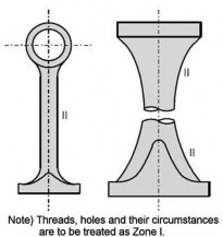
(a) Solid crankshaft
(b) Semi built-up crankshaft
Notes)
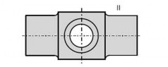
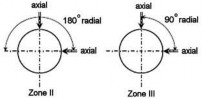
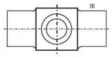
1. Where the crankpin or journal has oil holes, the circumferential surfaces of the oil holes are to be treated as Zone I. (See the figure in the right.)
2. In the above figures, "θ", "a" and "b" mean: θ= 60°
a = 1.5 r
b = 0.05 d (circumferential surfaces of shrinkage fit) where,
r : fillet radius
d : journal diameter
3. Identification of the Zones (Similar in Figs. 1 thru 4):
![]()
: Zone I
: Zone II
db : oil hole bore diameter
Fig 1 Zones for magnetic particle / liquid penetrant testing on crankshafts
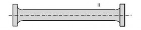
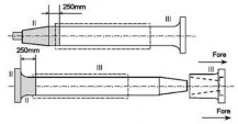
(b) Intermediate shaft

(a) Propeller shaft
(c) Thrust shaft
Note) For propeller shaft, intermediate shafts and thrust shafts, all areas with stress raisers such as radial holes, slots and key ways are to be treated as Zone I.
Fig 2 Zones for magnetic particle / liquid penetrant testing on shafts
![]()
64 Guidance Relating to the Rules for the Classification of Steel Ships 2015
![]()
(c) Cross head
(a) Connecting rod (b) Piston rod
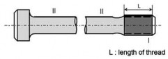
(d) Bolt
Fig 3 Zones for magnetic particle / liquid penetrant testing on machinery components
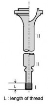
(a) Type A
(b) Type B
(c) Type C
Fig 4 Zones for magnetic particle / liquid penetrant testing on rudder stocks
(5) Surface Inspection
(a) Where indicated by Figs 1 to 4, magnetic particle inspection will be carried out with the following exceptions, when liquid penetrant testing will be permitted :
- austenitic stainless steels;
- interpretation of open visual or magnetic particle indications,
- at the instruction of the Surveyor.
(b) Unless otherwise specified in the order, the magnetic particle test shall be performed on a forging in the final machined surface condition and final thermally treated condition or with- in 0.3 mm of the final machined surface condition for A C techniques (0.8 mm for D C tech-
![]()
Guidance Relating to the Rules for the Classification of Steel Ships 2015 65
(c)
(d)
(e)
![]()
niques).
Unless otherwise agreed, the surface inspection is to be carried out in the presence of the Surveyor. The surface inspection is to be carried out before the shrink fitting, where applicable.
For magnetic particle testing, attention is to be paid to the contact between the forging and the clamping devices of stationary magnetization benches in order to avoid local overheating or burning damage in its surface. Prods shall not be permitted on finished machined items.
When indications were detected as a result of the surface inspection, acceptance or rejection
is to be decided in accordance with clause (6)
(6) Acceptance Criteria and Rectification of Defects
(A) Acceptance Criteria Visual Inspection
(a) All forgings shall be free of cracks, crack-like indications, laps, seams, folds, or other
injurious indications. At the request of the Surveyor, additional magnetic particle, liquid penetrant and ultrasonic testing may be required for a more detailed evaluation of sur- face irregularities.
(b) The bores of hollow propeller shafts are to be visually examined for imperfections un- covered by the machining operation. Machining marks are to be ground to a smooth profile.
(B) Acceptance Criteria Magnetic Particle Testing and Liquid Penetrant Testing
(a) The following definitions relevant to indications apply:
(i) Linear indication : an indication in which the length is at least three times the
width;
(ii) Nonlinear indication : an indication of circular or elliptical shape with a length less than three times the width;
(iii)Aligned indication : three or more indications in a line, separated by 2 mm or less edge-to-edge;
(iv)Open indication : an indication visible after removal of the magnetic particles or
that can be detected by the use of contrast dye penetrant;
(v) Non-open indication : an indication that the magnetic particles or that cannot be
trant,
(vi)Relevant indication : an indication that
is not visually detectable after removal of detected by the use of contrast dye pene-
is caused by a condition or type of dis-
continuity that requires evaluation. Only indications which
er than 1.5 mm shall be considered relevant.
have any dimension great-
(b) For the purpose of evaluating indications, the surface is to be divided into reference areas of 225 cm2. The area shall be taken in the most unfavorable location relative to the indication being evaluated.
(c) The allowable number and size of indications in the reference area is given in Table 1 for crankshaft forgings and in Table 2 for other forgings, respectively. Cracks are not acceptable. Irrespective of the results of non-destructive examination, the Surveyor may reject the forging if the total number of indications is excessive.
(C) Rectification of Defects
(a) Defects and unacceptable indications must be rectified as indicated below and detailed in
(i) thru (v)
(i) Defective parts of material may be removed by grinding, or by chipping and
grinding. All grooves shall have a bottom radius of approximately three times the groove depth and should be smoothly blended to the surface area with a finish equal to the adjacent surface.
(ii) To depress is to flatten or relieve the edges of a non-open indication with a fine pointed abrasive stone with the restriction that the depth beneath the original surface shall be 0.08 mm minimum to 0.25 mm maximum and that the depressions be blend- ed into the bearing surface. A depressed area is not considered a groove and is made only to prevent galling of bearings.
(iii)Non-open indications evaluated as segregation need not be rectified.
(iv)Complete removal of the defect is to be proved by magnetic particle testing or pen- etrant testing, as appropriate.
(v) Repair welding is not permitted for crankshafts. Repair welding of other forgings is
subjected to prior approval of the individual Class Society.
![]()
66 Guidance Relating to the Rules for the Classification of Steel Ships 2015
![]()
(b) Zone I in crankshaft forgings
Neither indications nor repair are permitted in this zone.
(c) Zone II in crankshaft forgings
(i) Indications must be removed by grinding to a depth no greater than 1.5 mm.
(ii) Indications detected in the journal bearing surfaces must be removed by grinding to a depth no greater than 3.0 mm. The total ground area shall be less than 1 % of the
total bearing surface area concerned.
(iii)Non-open indications, except those evaluated as segregation, shall be depressed
need not be removed.
but
Table 1 - Crankshaft forgings ; Allowable number and size of indications in a reference area of 225 cm2
Inspection Zone | Max. number of indications | Type of indication | Max. number for each type | Max. dimension (mm) |
I (critical fillet area) | 0 | Linear Nonlinear Aligned | 0 0 0 | - - - |
II (important fillet area) | 3 | Linear Nonlinear Aligned | 0 3 0 | - 3.0 - |
III (journal surfaces) | 3 | Linear Nonlinear Aligned | 0 3 0 | - 5.0 - |
Table 2 - Steel forgings excluding crankshaft forgings ; Allowable number and size of indications in a reference area of 225 cm2
Inspection Zone | Max. number of indications | Type of indication | Max. number for each type | Max. dimension (mm) |
I | 3 | Linear | 0(1) | - |
Nonlinear | 3 | 3.0 | ||
Aligned | 0(1) | - | ||
II | 10 | Linear | 3(1) | 3.0 |
Nonlinear | 7 | 5.0 | ||
Aligned | 3(1) | 3.0 | ||
Note: (1) Linear or aligned indications are not permitted on bolts, which receive a direct fluctuating load, e.g. main bearing bolts, connecting rod bolts, crosshead bearing bolts, cylinder cover bolts. | ||||
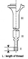
(d) Zone I in other forgings
Indications must be removed by grinding to a depth no greater than 1.5 mm. However, grinding is not permitted in way of finished machined threads.
(e) Zone II in other forgings
Indications must be removed by grinding to a depth no greater than 2 % of the diame- ter or 4.0 mm, whichever is smaller.
(f) Zones other than I and II in all forgings
Defects detected by visual inspection must be removed by grinding to a depth no great- er than 5 % of the diameter or 10mm, whichever is smaller. The total ground area shall be less than 2 % of the forging surface area.
![]()
Guidance Relating to the Rules for the Classification of Steel Ships 2015 67
![]()
(7) Record
Test results of surface inspections are to be recorded at least with the following items:
(a) Date of testing;
(b) Names and qualification level of inspection personnel;
(c) Kind of testing method;
- for liquid penetrant testing : test media combination
- for magnetic particle testing : method of magnetizing, test media and magnetic field strength
(d)
(e)
(f)
(g)
(h)
(i)
(j)
Kind of product;
Product number for identification; Grade of steel;
Heat treatment;
Stage of testing;
Position (zone) of testing; Surface condition;
(k) Test standards used;
(l)
Testing condition;
(m) Results;
(n) Statement of acceptance/non acceptance,
(o) Details of weld repair including sketch;
3. Ultrasonic testing
(1) General
(a) Volumetric inspection in this Guidance is to be carried out by ultrasonic testing using the contact method with straight beam and/or angle beam technique.
(b)
The testing procedures, apparatus and conditions of ultrasonic testing are to comply with the
recognized national or international standards. Generally the DG S(distance-gain size) proce- dure is to be applied using straight beam probes and/or angle beam probes with 2 to 4
MHz
and inspection should be carried out using a twin crystal 0° probe for near surface
scans (25 mm) plus an 0o probe for the remaining volume. Fillet radii should be examined
using 45°, 60° or 70° probes.
(c) Personnel engaged in ultrasonic testing is to be qualified in accordance with the Society’s
Rules. The qualification is to be verified by certificates.
(2) Products
(A) Volumetric inspections by ultrasonic testing generally apply to the following steel forgings :
(a) crankshaft with minimum crankpin diameter not less than 150 mm;
(b) propeller shafts, intermediate shafts, thrust shafts and rudder stocks with minimum diam- eter not less than 200 mm,
(c) connecting rods, piston rods and crosshead with minimum diameter not less than 200 mm or equivalent cross section.
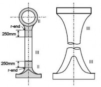
(3) Zones for ultrasonic testing
(A) Ultrasonic testing shall be carried out in the zones I to III as indicated in Figs 5 to 8.
Areas may be upgraded to a higher zone at the discretion of the Surveyors.
![]()
68 Guidance Relating to the Rules for the Classification of Steel Ships 2015
![]()
Scanning direction
(a) Solid crankshaft
(b) Semi built-up crankshaft
Note)
1. In the above figures, "a" and "b" mean: a = 0.1d or 25mm, whichever greater
b = 0.05d or 25mm, whichever greater (circumstances of shrinkage fit) where,
d : pin or journal diameter
2. Core areas of crank pins and/or journals within a radius of 0.25d between the webs may generally be coordinated to Zone II.
3. Identification of the Zones (Similar in Figs. 5 thru 8.):
![]()
: Zone I
: Zone II
: Zone III
Fig 5 Zones for ultrasonic testing on crankshafts
![]()
Scanning direction
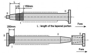
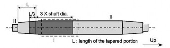
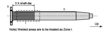
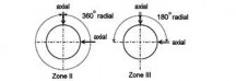
(a) Propeller shaft
(b) Intermediate shaft

(c) Thrust shaft
Notes)
1. For hollow shafts, 360° radial scanning applies to Zone III.
2. Circumferences of the bolt holes in the flanges are to be treated as Zone II.
Fig 6 Zones for ultrasonic testing on shafts
![]()
Guidance Relating to the Rules for the Classification of Steel Ships 2015 69
Scanning direction
![]()
(b) Piston rod
(a) Connecting rod (c) Cross head Fig 7 Zones for ultrasonic testing on machinery components
Scanning direction for Type A and Type B
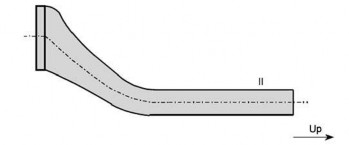
(a) Type A
(b) Type B
(c) Type C Scanning direction
Type C
Fig 8 Zones for ultrasonic testing on rudder stocks
![]()
70 Guidance Relating to the Rules for the Classification of Steel Ships 2015
![]()
(4) Surface Condition
(a) The surfaces of forgings to be examined are to be such that adequate coupling can be es- tablished between the probe and the forging and that excessive wear of the probe can be avoided. The surfaces are to be free from scale, dirt, grease or paint.
(b) The ultrasonic testing is to be carried out after the steel forgings have been machined to a condition suitable for this type of testing and after the final heat treatment , but prior to the drilling of the oil bores and prior to surface hardening. Black forgings shall be inspected af-
ter removal of the oxide scale by either flame descaling or shot blasting methods.
(5) Acceptance Criteria
(a) Acceptance criteria of volumetric inspection by ultrasonic
4.
testing are shown in Table 3 and
![]()
![]()
![]()
Table 3 Acceptance Criteria for Crankshafts
Type of Forging | Zone | Allowable disc shape according to DG S(1) | Allowable length of indication(2) | Allowable distance between two indications(3) |
Crank shaft | I II III | d 0.5 mm d 2.0 mm d 4.0 mm | - 10 mm 15 mm | - 20 mm 20 mm |
Notes : (1) DGS : Distance Gain Size evaluation system (2) The transference distance of the probe in the range where the echo height exceeds 50% of DGS line is taken as the length of indication. (3) In case of accumulations of two or more isolated indications which are subjected to registration the minimum distance between two neighboring indications must be at least the length of the bigger indication. This applies as well to the distance in axial direction as to the distance in depth. Isolated indications with less distances are to be determined as one single indication. | ||||
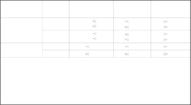
Table 4 Acceptance Criteria for Shafts and Machinery Components
Type of Forging Zone
Allowable disc shape according to DG S(1)(2)
Allowable length of indication(3)
Allowable distance between two indications(4)
Propeller shaft, intermediate shaft Thrust shaft,
outer: d 2 mm
II inner: d 4 mm
outer: d 3 mm
10 mm
15 mm
10 mm
20 mm
20 mm
20 mm
Rudder stock
III
inner: d 6 mm
15 mm
20 mm
Connecting rod, Piston rod, Crosshead
II d 2.0 mm 10 mm 20 mm
III d 4.0 mm 10 mm 20 mm
Notes :
(1) DGS : Distance Gain Size evaluation system
(2) Outer part means the part beyond one third of the shaft radius from the center, the inner part means the remaining core area.
(3) The transference distance of the probe in the range where the echo height exceeds 50% of DGS line is taken as the length of indication.
(4) In case of accumulations of two or more isolated indications which are subjected to registration the minimum distance between two neighboring indications must be at least the length of the bigger indication.
![]()
Guidance Relating to the Rules for the Classification of Steel Ships 2015 71
![]()
(6) Record
Test results of volumetric inspection are to be recorded at least with the following items:
(a)
(b)
(c)
(d)
(e)
(f)
(g)
(h)
(i)
(j)
(k)
(l)
Date of testing;
Names and qualification level of inspection Kind of testing method;
Kind of product;
Product number for identification; Grade of steel;
Heat treatment;
Stage of testing;
Position (zone) of testing; Surface condition;
Test standards used; Testing condition;
personnel;
(m) Results,
(n) Statement of acceptance/non acceptance; ![]()
![]()
72 Guidance Relating to the Rules for the Classification of Steel Ships 2015
![]()